Simple Way to Generate PDF File from LaTeX file:
Initial observations of users' sketched trusses.- link
Mechanics Sketch Research:
Observations of Sketched Trusses, Pt. 1:
Initial observations of users' sketched trusses.
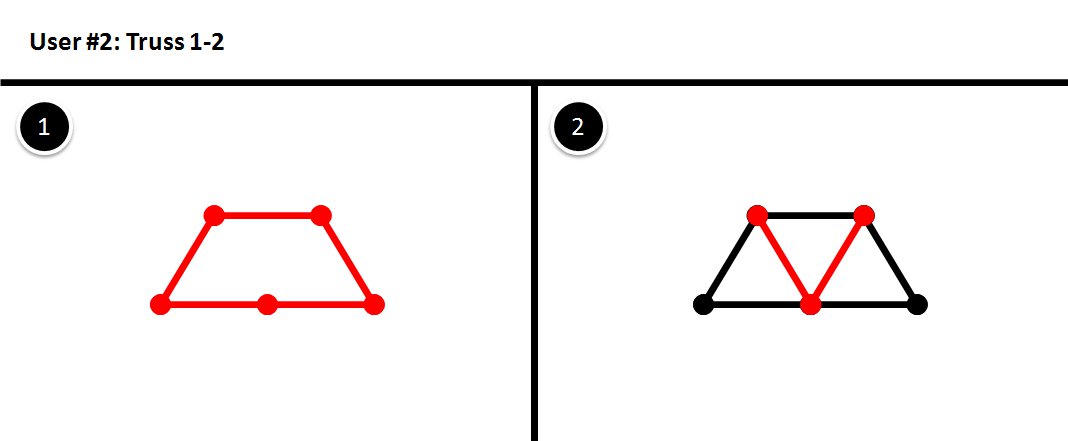
User Sketched Data of Truss 1-2:User Sketched Data of Truss 1-3:
User sketched data for Truss 1-3, which is a truss with 1 layer and contains 3 upward-pointing triangles in the top layer.
User Sketched Data of Truss 2-2:
User sketched data for Truss 2-2, which is a truss with 2 layers and contains 2 upward-pointing triangles in the top layer.